Raymarching Distance Fields: Concepts and Implementation in Unity
Technical Writeup Posted on 01 October 2016 by Flafla2
Raymarching is a fairly new technique used to render realtime scenes. The technique is particularly interesting because it is entirely computed in a screen-space shader. In other words, no mesh data is provided to the renderer and the scene is drawn on a single quad that covers the camera’s field of vision. Objects in the scene are defined by an analytic equation that describes the shortest distance between a point and the surface of any object in the scene (hence the full name Raymarching Distance Fields). It turns out that with only this information you can compose some strikingly complicated and beautiful scenes. Further, because you aren’t using polygonal meshes (and are instead using mathematical equations) it is possible to define perfectly smooth surfaces, unlike in a traditional renderer.

Snail by Inigo Quilez was created entirely using raymarching. You can find more examples of raymarched scenes on Shadertoy.
This article will first discuss the fundamental concepts and theory of raymarching. Then it will show how to implement a basic raymarcher in the Unity game engine. Finally it will show how to integrate raymarching practically in a real Unity game by allowing raymarched objects to be occluded by normal Unity GameObjects.
You can find a complete reference implementation at this Github Repository.
Table of Contents
- Introduction to Raymarching
- Implementing a Basic Raymarcher
- Adding Lighting
- Interacting With Mesh-Based Objects
- Fun with Distance Fields
- Closing Remarks
- References
Introduction to Raymarching
Raymarching is similar to traditional raytracing in that a ray is cast into the scene for each pixel. In a raytracer, you are given a set of equations that determine the intersection of a ray and the objects you are rendering. This way it is possible to find which objects the ray intersects (that is, the objects that the camera sees). It is also possible to render nonpolygonal objects such as spheres because you only need to know the sphere / ray intersection formula (for example). However, raytracing is very expensive, especially when you have many objects and complex lighting. Additionally you can not raytrace through volumetric materials, such as clouds and water. Therefore raytracing is largely inadequate for realtime applications.
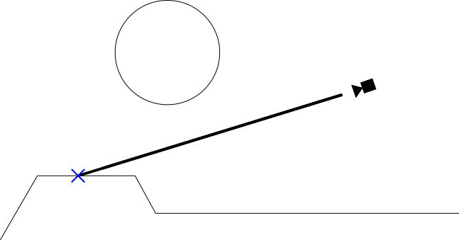
Figure 1: Simplified representation of a raytracer. The thick black line is an example ray cast to render a pixel from the camera.
Raymarching takes an alternative approach to the ray / object intersection problem. Raymarching does not try to directly calculate this intersection analytically. Instead, in raymarching we “march” a point along the ray until we find that the point intersects an object. It turns out that sampling this point along the ray is a relatively simple and inexpensive operation, and much more practical in realtime. As you can see in figure 2, this method is less accurate than raytracing (if you look closely the intersection point is slightly off). For games however it is more than adequate, and is a great compromise between the efficiency of polygonal rendering and the accuracy of traditional raytracing.
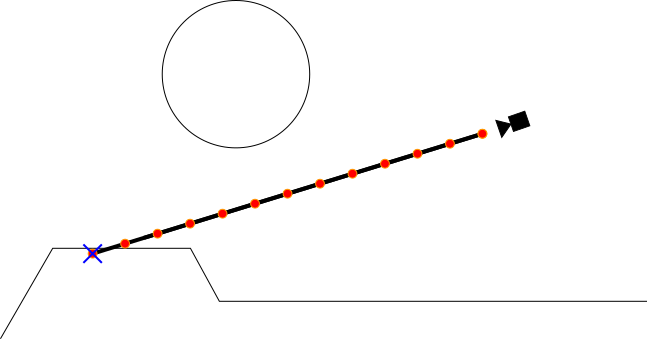
Figure 2: Basic implementation of a raymarcher with a fixed marching interval. The red dots represent each sample point.
Enter distance fields
A fixed interval raymarcher such as the one shown in Figure 2 is sufficient for many applications such as volumetric or transparent surfaces. However, for opaque objects we can introduce another optimization. This optimization calls for the use of signed distance fields. A distance field is a function that takes in a point as input and returns the shortest distance from that point to the surface any object in the scene. A signed distance field additionally returns a negative number if the input point is inside of an object. Distance fields are great because they allow us to limit how often we need to sample when marching along the ray. See the example below:
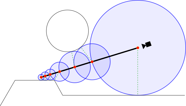
Figure 3: Visualization of a raymarcher using signed distance fields. The red dots represent each sample point. Each blue circle represents the area that is guaranteed to not contain any objects (because they are within the results of the distance field). The dashed green lines represent the true shortest vector between each sample point and the scene.
As you can see above, the distance field allows us to march the ray by a maximal distance each step.
Implementing a Basic Raymarcher
Because the raymarching algorithm is run on every pixel, a raymarcher in Unity is essentially a post processing shader. Because of this, much of the C# code that we will write is similar to what you would use for a full-screen image effect.
Setting up the Image Effect Script
Let’s implement a basic image effect loading script. A quick note: I am using the SceneViewFilter script to automatically apply image filters to the scene view. This allows you to debug your shader more easily. To use it, simply extend SceneViewFilter instead of MonoBehaviour in your image effect script.
Just to get the boilerplate code out of the way, a basic image effect script is shown below:
1
2
3
4
5
6
7
8
9
10
11
12
13
14
15
16
17
18
19
20
21
22
23
24
25
26
27
28
29
30
31
32
33
34
35
36
37
38
39
40
41
42
43
44
45
46
47
48
49
using UnityEngine;
using System.Collections;

[ExecuteInEditMode]
[RequireComponent(typeof(Camera))]
[AddComponentMenu("Effects/Raymarch (Generic)")]
public class TutorialRaymarch : SceneViewFilter {

    [SerializeField]
    private Shader _EffectShader;

    public Material EffectMaterial
    {
        get
        {
            if (!_EffectMaterial && _EffectShader)
            {
                _EffectMaterial = new Material(_EffectShader);
                _EffectMaterial.hideFlags = HideFlags.HideAndDontSave;
            }

            return _EffectMaterial;
        }
    }
    private Material _EffectMaterial;

    public Camera CurrentCamera
    {
        get
        {
            if (!_CurrentCamera)
                _CurrentCamera = GetComponent<Camera>();
            return _CurrentCamera;
        }
    }
    private Camera _CurrentCamera;

    [ImageEffectOpaque]
    void OnRenderImage(RenderTexture source, RenderTexture destination)
    {
        if (!EffectMaterial)
        {
            Graphics.Blit(source, destination); // do nothing
            return;
        }

        Graphics.Blit(source, destination, EffectMaterial, 0); // use given effect shader as image effect
    }
}
To use this script, attach it to a camera and drag an image effect shader onto the “Effect Shader” field. As a test, you can try the default image effect shader (Assets > Create > Shader > Image Effects Shader), which simply inverts the screen. With that out of the way, we can begin to get into the more technical aspects of the implementation.
Passing Rays to the Fragment Shader
The first step in actually implementing a raymarcher is to calculate the ray that we will be using for each pixel. We also want these rays to match up with the Unity render settings (such as the camera’s postion, rotation, FOV, etc).
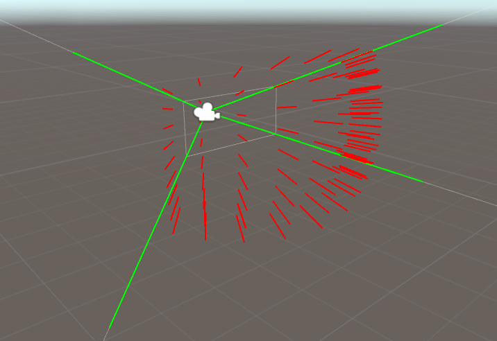
Figure 4: A visualization of the rays sent out from the camera
There are many ways of doing this, but I have chosen to use the following procedure every frame:
- Compute an array of four vectors that make up Camera View Frustum. These four vectors can be thought of as the “corners” of the view frustum:
The four view frustum corners that are later passed to the shader - When rendering our raymarcher as an image effect shader, use our own custom replacement for Graphics.Blit(). Graphics.Blit essentially renders a quad over the entire screen, and this quad renders with the image effect shader. We will add to this by, for each vertex, passing the corresponding indices in the array we created in step 1. Now, the vertex shader is aware of the rays to cast at each corner of the screen!
- In the shader, pass the ray directions from step 2 into the fragment shader. Cg will automatically interpolate the ray directions for each pixel, giving the true ray direction.
Okay, now let’s implement the above process.
Step 1: Computing the View Frustum corners
To calculate the camera frustum corner rays, you have to take into account the field of view of the camera as well as the camera’s aspect ratio. I have done this in the function GetFrustumCorners below:
1
2
3
4
5
6
7
8
9
10
11
12
13
14
15
16
17
18
19
20
21
22
23
24
25
26
27
28
29
30
31
32
33
/// \brief Stores the normalized rays representing the camera frustum in a 4x4 matrix.  Each row is a vector.
///
/// The following rays are stored in each row (in eyespace, not worldspace):
/// Top Left corner:     row=0
/// Top Right corner:    row=1
/// Bottom Right corner: row=2
/// Bottom Left corner:  row=3
private Matrix4x4 GetFrustumCorners(Camera cam)
{
    float camFov = cam.fieldOfView;
    float camAspect = cam.aspect;

    Matrix4x4 frustumCorners = Matrix4x4.identity;

    float fovWHalf = camFov * 0.5f;

    float tan_fov = Mathf.Tan(fovWHalf * Mathf.Deg2Rad);

    Vector3 toRight = Vector3.right * tan_fov * camAspect;
    Vector3 toTop = Vector3.up * tan_fov;

    Vector3 topLeft = (-Vector3.forward - toRight + toTop);
    Vector3 topRight = (-Vector3.forward + toRight + toTop);
    Vector3 bottomRight = (-Vector3.forward + toRight - toTop);
    Vector3 bottomLeft = (-Vector3.forward - toRight - toTop);

    frustumCorners.SetRow(0, topLeft);
    frustumCorners.SetRow(1, topRight);
    frustumCorners.SetRow(2, bottomRight);
    frustumCorners.SetRow(3, bottomLeft);

    return frustumCorners;
}
It’s worth noting a couple of things about this function. First, it returns a Matrix4x4 instead of an array of Vector3’s. This way, we can pass the vectors to our shader with a single variable (without having to use arrays). Second, it returns the frustum corner rays in eye space. This means that (0,0,0) is assumed to be the camera’s position, and the rays themselves are from the Camera’s point of view (instead of, for example, worldspace).
Step 2: Passing the Rays to the GPU
To pass this matrix to the shader, we need to make a slight modification to our Image Effect Script:
1
2
3
4
5
6
7
8
9
10
11
12
13
14
15
16
[ImageEffectOpaque]
void OnRenderImage(RenderTexture source, RenderTexture destination)
{
    if (!EffectMaterial)
    {
        Graphics.Blit(source, destination); // do nothing
        return;
    }

    // pass frustum rays to shader
    EffectMaterial.SetMatrix("_FrustumCornersES", GetFrustumCorners(CurrentCamera));
    EffectMaterial.SetMatrix("_CameraInvViewMatrix", CurrentCamera.cameraToWorldMatrix);
    EffectMaterial.SetVector("_CameraWS", CurrentCamera.transform.position);

    Graphics.Blit(source, destination, EffectMaterial, 0); // use given effect shader as image effect
}
Later, when we work on the image effect shader itself, we can access this matrix using the uniform _FrustumCornersES. I also threw in some camera-related information that we will need later (_CameraInvViewMatrix will be used to convert the rays from eye space to world space, and _CameraWS is the camera’s position).
Next up, we need to give the vertex shader the tools to interpret this matrix correctly. Remember: an image effect is simply a quad drawn over the entire screen, so we need to somehow pass the corresponding index of _FrustumCornersES to each vertex in the vertex shader. To do this, we need to use our own custom replacement to Graphics.Blit (line 13 above). In this custom version, we will use a sneaky trick: because the quad in Graphics.Blit is drawn using Orthographic Projection, the z position of each vertex doesn’t affect the final image. So, we can simply pass the corresponding indices of _FrustumCornersES through the z coordinate of each vertex! This sounds complicated, but is quite simple in practice:
1
2
3
4
5
6
7
8
9
10
11
12
13
14
15
16
17
18
19
20
21
22
23
24
25
26
27
28
29
30
31
32
33
34
35
36
37
38
39
40
41
42
43
44
45
46
47
48
49
50
51
/// \brief Custom version of Graphics.Blit that encodes frustum corner indices into the input vertices.
///
/// In a shader you can expect the following frustum cornder index information to get passed to the z coordinate:
/// Top Left vertex:     z=0, u=0, v=0
/// Top Right vertex:    z=1, u=1, v=0
/// Bottom Right vertex: z=2, u=1, v=1
/// Bottom Left vertex:  z=3, u=1, v=0
///
/// \warning You may need to account for flipped UVs on DirectX machines due to differing UV semantics
///          between OpenGL and DirectX.  Use the shader define UNITY_UV_STARTS_AT_TOP to account for this.
static void CustomGraphicsBlit(RenderTexture source, RenderTexture dest, Material fxMaterial, int passNr)
{
    RenderTexture.active = dest;

    fxMaterial.SetTexture("_MainTex", source);

    GL.PushMatrix();
    GL.LoadOrtho(); // Note: z value of vertices don't make a difference because we are using ortho projection

    fxMaterial.SetPass(passNr);

    GL.Begin(GL.QUADS);

    // Here, GL.MultitexCoord2(0, x, y) assigns the value (x, y) to the TEXCOORD0 slot in the shader.
    // GL.Vertex3(x,y,z) queues up a vertex at position (x, y, z) to be drawn.  Note that we are storing
    // our own custom frustum information in the z coordinate.
    GL.MultiTexCoord2(0, 0.0f, 0.0f);
    GL.Vertex3(0.0f, 0.0f, 3.0f); // BL

    GL.MultiTexCoord2(0, 1.0f, 0.0f);
    GL.Vertex3(1.0f, 0.0f, 2.0f); // BR

    GL.MultiTexCoord2(0, 1.0f, 1.0f);
    GL.Vertex3(1.0f, 1.0f, 1.0f); // TR

    GL.MultiTexCoord2(0, 0.0f, 1.0f);
    GL.Vertex3(0.0f, 1.0f, 0.0f); // TL

    GL.End();
    GL.PopMatrix();
}

// ...

void OnRenderImage(RenderTexture source, RenderTexture destination)
{
    // ...
    EffectMaterial.SetMatrix("_FrustumCornersES", GetFrustumCorners(CurrentCamera));

    CustomGraphicsBlit(source, destination, EffectMaterial, 0); // Replace Graphics.Blit with CustomGraphicsBlit
}
In a normal Graphics.Blit implementation, the four calls to GL.Vertex3 would all have z coordinates of 0. However, with this modification, we assign the corresponding indices in _FrustumCornersES as the z coordinate.
Step 3: Receiving the Ray Directions in your Shader
Finally, we are now ready to start writing the raymarching shader. As a base, I will start with the default image effects shader (Assets > Create > Shader > Image Effects Shader). First, we need to edit the vertex shader to properly interpret _FrustumCornersES:
1
2
3
4
5
6
7
8
9
10
11
12
13
14
15
16
17
18
19
20
21
22
23
24
25
26
27
28
29
30
31
32
33
34
35
36
37
38
39
40
41
42
43
44
45
46
// Provided by our script
uniform float4x4 _FrustumCornersES;
uniform sampler2D _MainTex;
uniform float4 _MainTex_TexelSize;
uniform float4x4 _CameraInvViewMatrix;

// Input to vertex shader
struct appdata
{
    // Remember, the z value here contains the index of _FrustumCornersES to use
    float4 vertex : POSITION;
    float2 uv : TEXCOORD0;
};

// Output of vertex shader / input to fragment shader
struct v2f
{
    float4 pos : SV_POSITION;
    float2 uv : TEXCOORD0;
    float3 ray : TEXCOORD1;
};

v2f vert (appdata v)
{
    v2f o;

    // Index passed via custom blit function in RaymarchGeneric.cs
    half index = v.vertex.z;
    v.vertex.z = 0.1;

    o.pos = mul(UNITY_MATRIX_MVP, v.vertex);
    o.uv = v.uv.xy;

    #if UNITY_UV_STARTS_AT_TOP
    if (_MainTex_TexelSize.y < 0)
        o.uv.y = 1 - o.uv.y;
    #endif

    // Get the eyespace view ray (normalized)
    o.ray = _FrustumCornersES[(int)index].xyz;

    // Transform the ray from eyespace to worldspace
    // Note: _CameraInvViewMatrix was provided by the script
    o.ray = mul(_CameraInvViewMatrix, o.ray);
    return o;
}
Much of the vertex shader so far should be familiar to Unity graphics programmers: as in most image effect shaders we pass the vertex positions and UV data to the fragment shader. We also need to flip the UVs in the Y axis in some cases to prevent our output appearing upside-down. Of course, we also extract the corresponding ray from _FrustumCornersES that we are interested in, using the Z coordinate of the input vertex (these Z values were injected above in Step 2). After the vertex shader finishes, the rays are interpolated by the GPU for each pixel. We can now use these interpolated rays in the fragment shader!
As a test, try simply returning the ray direction in the fragment shader, like so:
1
2
3
4
5
fixed4 frag (v2f i) : SV_Target
{
    fixed4 col = fixed4(i.ray, 1);
    return col;
}
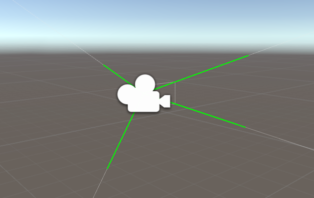
You should see the following visualization back in Unity:
Visualizing the world-space ray direction of each pixel. Notice that, for example, when you look up the result is green. This corresponds to the actual ray direction (0, 1, 0).
Building the Distance Field
The next step is to construct the distance field that we are going to use. As a reminder, the distance field defines what you are going to render (as opposed to 3D models/meshes in a traditional renderer). Your distance field function takes in a point as input, and returns the distance from that point to the surface of the closest object in the scene. If the point is inside an object, the distance field is negative.
Constructing a distance field is an incredibly involved and complex topic that is perhaps beyond the scope of this article. Luckily, there are some excellent resources online about distance fields, such as this excellent resource from Inigo Quilez listing a number of common distance field primatives. For the purposes of this article, I will borrow from Inigo and draw a simple torus at the origin of the scene:
1
2
3
4
5
6
7
8
9
10
11
12
13
14
15
16
// Torus
// t.x: diameter
// t.y: thickness
// Adapted from: http://iquilezles.org/www/articles/distfunctions/distfunctions.htm
float sdTorus(float3 p, float2 t)
{
    float2 q = float2(length(p.xz) - t.x, p.y);
    return length(q) - t.y;
}

// This is the distance field function.  The distance field represents the closest distance to the surface
// of any object we put in the scene.  If the given point (point p) is inside of an object, we return a
// negative answer.
float map(float3 p) {
    return sdTorus(p, float2(1, 0.2));
}
In this case, map defines the distance field that describes a torus with diameter 1.0 and thickness 0.2, located at the origin of the scene. This map function is perhaps the most creative and fun aspect of raymarching, so I recommend you have fun with it! Try new primitives out, combinations of primitives, or even your own weird custom shapes! Once again, you should check out this resource for more distance field equations.
Writing the Raymarch Function
Now that we have built a distance field to sample, we can write the core raymarch loop. This loop will be called from the fragment shader, and as explained at the top of this post, is responsible for “marching” a sample point along the current pixel’s ray. The raymarch function returns a color: the color of whatever object the ray hits (or a completely transparent color if no object is found). The raymarch function essentially boils down to a simple for loop, as shown below:
1
2
3
4
5
6
7
8
9
10
11
12
13
14
15
16
17
18
19
20
21
22
23
24
25
26
27
28
// Raymarch along given ray
// ro: ray origin
// rd: ray direction
fixed4 raymarch(float3 ro, float3 rd) {
    fixed4 ret = fixed4(0,0,0,0);

    const int maxstep = 64;
    float t = 0; // current distance traveled along ray
    for (int i = 0; i < maxstep; ++i) {
        float3 p = ro + rd * t; // World space position of sample
        float d = map(p);       // Sample of distance field (see map())

        // If the sample <= 0, we have hit something (see map()).
        if (d < 0.001) {
            // Simply return a gray color if we have hit an object
            // We will deal with lighting later.
            ret = fixed4(0.5, 0.5, 0.5, 1);
            break;
        }

        // If the sample > 0, we haven't hit anything yet so we should march forward
        // We step forward by distance d, because d is the minimum distance possible to intersect
        // an object (see map()).
        t += d;
    }

    return ret;
}
In each iteration of the raymarch loop, we sample a point along the ray. If we hit something, then bail out of the loop and return a color (in other words, the color of the object). If we don’t hit anything (the result of map is greater than zero) then we move forward by the distance given to us by the distance field. If you’re confused, revisit the theory discussed at the beginning of the article.
If you find yourself building extremely complex scenes with lots of small details, you may need to increase the maxstep constant on line 7 (at an increased performance cost). You also might want to carefully tweak maxstep anyway to see how many samples you can get away with (64 samples in this case is overkill for a simple torus, but for the sake of example I’ll keep it).
Now all that’s left is to call raymarch() from the fragment shader. This is simply done like so:
1
2
3
4
5
6
7
8
9
10
11
12
13
14
15
16
17
18
// Provided by our script
uniform float3 _CameraWS;

// ...

fixed4 frag (v2f i) : SV_Target
{
    // ray direction
    float3 rd = normalize(i.ray.xyz);
    // ray origin (camera position)
    float3 ro = _CameraWS;

    fixed3 col = tex2D(_MainTex,i.uv); // Color of the scene before this shader was run
    fixed4 add = raymarch(ro, rd);

    // Returns final color using alpha blending
    return fixed4(col*(1.0 - add.w) + add.xyz * add.w,1.0);
}
All we are doing here is receiving our ray data from the vertex shader and passing it along to raymarch(). We finally blend the result with _MainTex (the rendered scene before applying this shader) using standard alpha blending. Recall that _CameraWS represents the world-space position of the camera and was passed to the shader as a uniform earlier in our C# script.
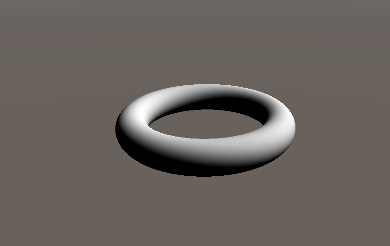
Open up Unity again, and behold! A torus!
Look mom, no polygons!
Adding Lighting
We have made some great progress thus far: by now we can render arbitrary shapes with infinite resolution using raymarching. However, of course, it would be hard to actually use raymarched objects in a game without being able to light them (except, I guess, in some sort of abstract game).
To perform any sort of lighting calculation of an object, you must first calculate the normals of that object. This is because light reflects off of objects as a function of their normals. More concretely, any BDRF requires the normal of the surface as input. In a normal polygonal 3D mesh, it is easy to find the normals of the object, because finding the normals of a triangle is an easily solved problem. However, in our case finding the normals of an object inside of a distance field isn’t so obvious.
It turns out that, at any point on a surface defined in the distance field, the gradient of the distance field is the same as the normals of the object at that point. The gradient of a scalar field (such as a signed distance field) is essentially the derivative of the field in the x, y, and z directions. In other words, for each dimension d we fix the other two dimensions and approximate the derivative of the field along d. Intuitively, the distance field value grows fastest when moving directly away from an object (that is, along it’s normal). So, by calculating the gradient at some point we have also calculated the surface normal at that point.
Here is how we approximate this gradient in code:
1
2
3
4
5
6
7
8
9
10
11
12
13
14
15
float3 calcNormal(in float3 pos)
{
    // epsilon - used to approximate dx when taking the derivative
    const float2 eps = float2(0.001, 0.0);

    // The idea here is to find the "gradient" of the distance field at pos
    // Remember, the distance field is not boolean - even if you are inside an object
    // the number is negative, so this calculation still works.
    // Essentially you are approximating the derivative of the distance field at this point.
    float3 nor = float3(
        map(pos + eps.xyy).x - map(pos - eps.xyy).x,
        map(pos + eps.yxy).x - map(pos - eps.yxy).x,
        map(pos + eps.yyx).x - map(pos - eps.yyx).x);
    return normalize(nor);
}
Be careful however, because this technique is quite expensive! You have to calculate your distance field a total of 6 extra times for each pixel in order to find the gradient.
Now that we have the ability to find the normals of objects, we can begin to light things! Of course, we need a light source first. In order to pass a light source to our shader, we need to modify our scripts a bit:
1
2
3
4
5
6
7
8
9
10
11
12
13
14
15
16
17
18
19
20
21
22
23
// ...

public class TutorialRaymarch : SceneViewFilter {

    // ...

    public Transform SunLight;

    // ...

    void OnRenderImage(RenderTexture source, RenderTexture destination)
    {
        // ...

        EffectMaterial.SetVector("_LightDir", SunLight ? SunLight.forward : Vector3.down);

        // ...

        CustomGraphicsBlit(source, destination, EffectMaterial, 0);
    }

    // ...
}
These additions simply pass along a vector to our shader that describes the direction of the sun. You can pass along more information (such as light intensity, color, etc.) if you would like, but we’ll keep it simple for now and assume that it is a simple white directional light with intensity 1.0. This vector is passed to our scripts by the shader uniform _LightDir. We can now use _LightDir along with calcNormal() to light our objects:
1
2
3
4
5
6
7
8
9
10
11
12
13
14
15
16
17
18
19
20
21
22
23
24
25
26
27
28
29
30
31
32
// ...

uniform float3 _LightDir;

// ...

fixed4 raymarch(float3 ro, float3 rd) {
    fixed4 ret = fixed4(0,0,0,0);

    const int maxstep = 64;
    float t = 0; // current distance traveled along ray
    for (int i = 0; i < maxstep; ++i) {
        float3 p = ro + rd * t; // World space position of sample
        float d = map(p);       // Sample of distance field (see map())

        // If the sample <= 0, we have hit something (see map()).
        if (d < 0.001) {
            // Lambertian Lighting
            float3 n = calcNormal(p);
            ret = fixed4(dot(-_LightDir.xyz, n).rrr, 1);
            break;
        }

        // If the sample > 0, we haven't hit anything yet so we should march forward
        // We step forward by distance d, because d is the minimum distance possible to intersect
        // an object (see map()).
        t += d;
    }
    return ret;
}

// ...
We use the Lambertian Reflectance Model above on lines 18-20, but you could use any BDRF that you want (just like with normal 3D models!). Back in the Unity editor, assign the script’s “Sun Light” attribute to a directional light in the scene, and you will find a very nicely lit torus indeed:
Our torus with lambertian lighting
Interacting With Mesh-Based Objects
So now you have constructed a bunch of objects using distance fields and you are ready to integrate them into your Unity project. However, you run into a major problem very quickly: Mesh-based objects and raymarched objects can’t interact with or touch each other! In fact, the raymarched objects always float on top of everything else, because our raymarcher doesn’t take depth into account. The video below illustrates this:
My brain hurts...
To fix this problem, we need to find the distance along each ray at which the closest mesh-based object lies. If our raymarch loop marches past this point, we bail out and render that object instead (because it is in front of any potential raymarched objects).
To find this distance, we need to take advantage of the depth buffer. The depth buffer is accessible to all image effects shaders and stores the eyespace depth of the closest object in the scene for each pixel. Refer to figure 5 below for more context.
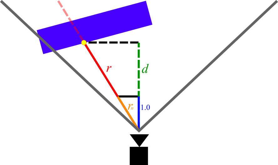
Figure 5: Diagram of the measurements we are interested in when calculating depth. The red line is the ray for some arbitrary pixel.
In Figure 5, the magnitude of r is the measurement that we are trying to find (depth beyond which we should bail out in the raymarch loop). The magnitude of d is the eyespace depth that is given to us for that pixel by the depth buffer (note that d is shorter than r, because d does not account for perspective).
In order to find the magnitude of r we can simply leverage the rules of similar triangles. Consider rn, the vector with the same direction as r but with length 1.0 in the z direction. We can write rn as:
In the above equation, rd is the vector with the same direction as r but with an arbitrary length (in other words, the ray vector that our shader is given). Clearly, from Figure 5 r and rn create two similar triangles. By multiplying rn by d (which we know from the depth buffer) we can derive r and its magnitude as follows:
| r | = rd × d
Using the depth buffer in our shader
Now we need to make some modifications to our code to align with the above theory. First, we need to make some changes to our vertex shader so that it returns rn instead of rd:
1
2
3
4
5
6
7
8
9
10
11
12
13
14
v2f vert (appdata v)
{
    // ...

    // Dividing by z "normalizes" it in the z axis
    // Therefore multiplying the ray by some number i gives the viewspace position
    // of the point on the ray with [viewspace z]=i
    o.ray /= abs(o.ray.z);

    // Transform the ray from eyespace to worldspace
    o.ray = mul(_CameraInvViewMatrix, o.ray);

    return o;
}
Note that we are dividing by abs(o.ray.z) instead of simply o.ray.z. This is because in eyespace coordinates, z < 0 corresponds to the forward direction. If we were to divide by a negative number, the ray direction would flip when dividing (and therefore the entire raymarched scene would appear flipped).
The final step is to integrate depth into our fragment shader and raymarch loop:
1
2
3
4
5
6
7
8
9
10
11
12
13
14
15
16
17
18
19
20
21
22
23
24
25
26
27
28
29
30
31
32
33
34
35
36
37
38
39
40
41
42
43
44
45
46
47
48
49
50
51
52
53
// Raymarch along given ray
// ro: ray origin
// rd: ray direction
// s: unity depth buffer
fixed4 raymarch(float3 ro, float3 rd, float s) {
    fixed4 ret = fixed4(0,0,0,0);

    const int maxstep = 64;
    float t = 0; // current distance traveled along ray
    for (int i = 0; i < maxstep; ++i) {
        // If we run past the depth buffer, stop and return nothing (transparent pixel)
        // this way raymarched objects and traditional meshes can coexist.
        if (t >= s) {
            ret = fixed4(0, 0, 0, 0);
            break;
        }

        // ...
    }

    return ret;
}

// ...
uniform sampler2D _CameraDepthTexture;
// ...

fixed4 frag (v2f i) : SV_Target
{
    // ray direction
    float3 rd = normalize(i.ray.xyz);
    // ray origin (camera position)
    float3 ro = _CameraWS;

    float2 duv = i.uv;
    #if UNITY_UV_STARTS_AT_TOP
    if (_MainTex_TexelSize.y < 0)
        duv.y = 1 - duv.y;
    #endif

    // Convert from depth buffer (eye space) to true distance from camera
    // This is done by multiplying the eyespace depth by the length of the "z-normalized"
    // ray (see vert()).  Think of similar triangles: the view-space z-distance between a point
    // and the camera is proportional to the absolute distance.
    float depth = LinearEyeDepth(tex2D(_CameraDepthTexture, duv).r);
    depth *= length(i.ray.xyz);

    fixed3 col = tex2D(_MainTex,i.uv);
    fixed4 add = raymarch(ro, rd, depth);

    // Returns final color using alpha blending
    return fixed4(col*(1.0 - add.w) + add.xyz * add.w,1.0);
}
On line 45, we access Unity’s depth texture using the standard Unity shader uniform _CameraDepthTexture, and convert it to eyespace depth using LinearEyeDepth(). For more information about depth textures and Unity, see this page from the Unity Manual. Next, on line 46, we multiply the depth by the length of rn, which was passed to us by the vertex shader, satisfying the equations discussed above.
We then pass the depth as a new parameter to raymarch(). In the raymarch loop, we bail out and return a completely transparent color if we march past the value given by the depth buffer (see lines 13-16). Now, when we check back in Unity, our raymarched objects coexist with normal mesh-based objects as expected:
Fun with Distance Fields
Now that we have our raymarcher up and running, we can start to build scenes! As I said earlier, this is a very deep rabbit hole and it is beyond the scope of this article to explore distance field construction entirely. However, below are some simple techniques that I have tried out. I recommend you check out some examples on Shadertoy to spark your imagination. In any case, below is a small sampler of some of the things that you can do:
Basic Transformations
Just like with mesh-based 3D models, you can perform transformations on an object using a model matrix. In our case however, we need to compute the inverse of the model matrix since we aren’t actually transforming the model itself. Rather, we are transforming the point that is used to sample our distance field.
To implement these transformations, we first build the model matrix in the image effect script and pass the inverse to the shader:
1
2
3
4
5
6
7
8
9
10
11
12
13
14
15
16
17
18
19
[ImageEffectOpaque]
void OnRenderImage(RenderTexture source, RenderTexture destination)
{
    // ...

    // Construct a Model Matrix for the Torus
    Matrix4x4 MatTorus = Matrix4x4.TRS(
        Vector3.right * Mathf.Sin(Time.time) * 5,
        Quaternion.identity,
        Vector3.one);
    MatTorus *= Matrix4x4.TRS(
        Vector3.zero,
        Quaternion.Euler(new Vector3(0, 0, (Time.time * 200) % 360)),
        Vector3.one);
    // Send the torus matrix to our shader
    EffectMaterial.SetMatrix("_MatTorus_InvModel", MatTorus.inverse);

    // ...
}
Note how you can use Time.time to animate objects. You can also use any variables from your script (including, concievably, Unity’s animation system) to inform these transformations. Next, we receive the Model Matrix in our shader and apply it to the torus:
1
2
3
4
5
6
7
uniform float4x4 _MatTorus_InvModel;

float map(float3 p) {
    float4 q = mul(_MatTorus_InvModel, float4(p,1));

    return sdTorus(q.xyz, float2(1, 0.2));
}
You’ll notice that the torus now moves nicely back and forth in Unity (enter play mode to see the animation):
Combining Objects
You can combine objects as well to create more complex forms. To do this, you simply need to take advantage of some simple distance field combine operations: opU() (Union), opI() (Intersection), and opS() (Subtraction). Below is an example distance field function that demonstrates the outcomes of these operations:
1
2
3
4
5
6
7
8
9
10
11
12
13
14
15
16
17
18
19
20
21
22
23
24
25
26
27
28
29
30
31
32
33
34
35
36
37
38
39
40
41
42
43
44
45
46
47
48
49
50
// Box
// b: size of box in x/y/z
// Adapted from: http://iquilezles.org/www/articles/distfunctions/distfunctions.htm
float sdBox(float3 p, float3 b)
{
    float3 d = abs(p) - b;
    return min(max(d.x, max(d.y, d.z)), 0.0) +
        length(max(d, 0.0));
}

// Union
// Adapted from: http://iquilezles.org/www/articles/distfunctions/distfunctions.htm
float opU( float d1, float d2 )
{
    return min(d1,d2);
}

// Subtraction
// Adapted from: http://iquilezles.org/www/articles/distfunctions/distfunctions.htm
float opS( float d1, float d2 )
{
    return max(-d1,d2);
}

// Intersection
// Adapted from: http://iquilezles.org/www/articles/distfunctions/distfunctions.htm
float opI( float d1, float d2 )
{
    return max(d1,d2);
}

float map(float3 p) {
    float union_box = opU(
        sdBox(p - float3(-4.5, 0.5, 0), float3(1,1,1)),
        sdBox(p - float3(-3.5, -0.5, 0), float3(1,1,1))
    );
    float subtr_box = opS(
        sdBox(p - float3(-0.5, 0.5, 0), float3(1,1,1.01)),
        sdBox(p - float3(0.5, -0.5, 0), float3(1,1,1))
    );
    float insec_box = opI(
        sdBox(p - float3(3.5, 0.5, 0), float3(1,1,1)),
        sdBox(p - float3(4.5, -0.5, 0), float3(1,1,1))
    );

    float ret = opU(union_box, subtr_box);
    ret = opU(ret, insec_box);

    return ret;
}
The result of this in Unity is shown below:
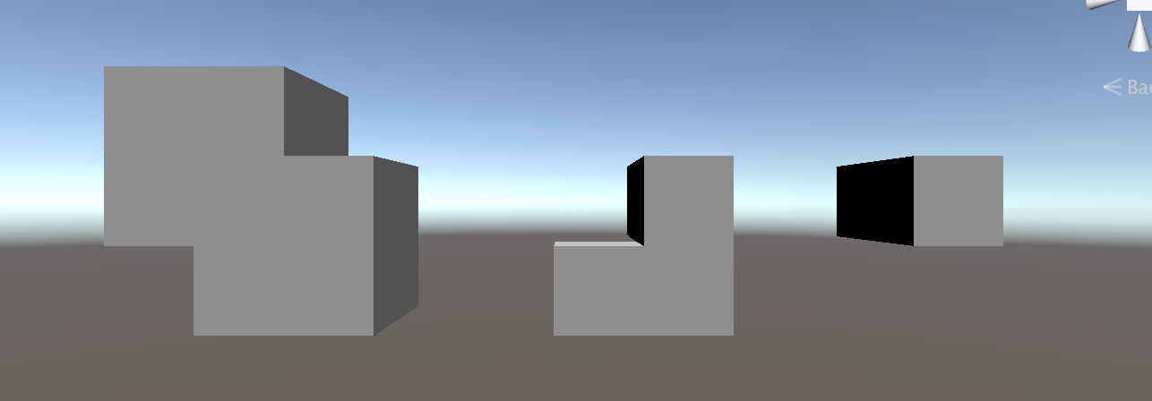
From Left to Right: Union, Subtraction, and Intersection Operators
Multiple Materials
You can extend your distance field function to return material data as well. Simply have your map() function return the relevant material information for each object - in the example below, we pull from a color ramp texture to pick which color each object is. We also need to modify the opU() function introduced above to support multiple materials.

The Color Ramp I am using.
As always, we need to pass the color ramp to our shader through the image effect script:
1
2
3
4
5
6
7
8
9
10
11
12
13
14
[SerializeField]
private Texture2D _ColorRamp;

// ...

[ImageEffectOpaque]
void OnRenderImage(RenderTexture source, RenderTexture destination)
{
    // ...

    EffectMaterial.SetTexture("_ColorRamp", _ColorRamp);

    // ...
}
Next we can use the new _ColorRamp uniform in the shader. As mentioned, we need to modify map() as well as the lighting calculation in raymarch() to leverage these different material properties.
1
2
3
4
5
6
7
8
9
10
11
12
13
14
15
16
17
18
19
20
21
22
23
24
25
26
27
28
29
30
31
32
33
34
35
36
37
38
39
40
41
42
43
44
45
46
47
48
49
50
51
uniform sampler2D _ColorRamp;

// ...

// Union (with material data)
float2 opU( float2 d1, float2 d2 )
{
    return (d1.x < d2.x) ? d1 : d2;
}

// Notice how map() now returns a float2
// \return.x: Distance field value
// \return.y: Color of closest object (0 - 1)
float2 map(float3 p) {
    float2 d_torus = float2(sdTorus(p, float2(1, 0.2)), 0.5);
    float2 d_box = float2(sdBox(p - float3(-3,0,0), float3(0.75,0.5,0.5)), 0.25);
    float2 d_sphere = float2(sdSphere(p - float3(3,0,0), 1), 0.75);

    float2 ret = opU(d_torus, d_box);
    ret = opU(ret, d_sphere);

    return ret;
}

fixed4 raymarch(float3 ro, float3 rd, float s) {
    fixed4 ret = fixed4(0,0,0,0);

    const int maxstep = 64;
    float t = 0; // current distance traveled along ray
    for (int i = 0; i < maxstep; ++i) {
        // ...

        float3 p = ro + rd * t; // World space position of sample
        float2 d = map(p);      // Sample of distance field (see map())
                                // d.x: distance field output
                                // d.y: material data

        // If the sample <= 0, we have hit something (see map()).
        if (d.x < 0.001) {
            float3 n = calcNormal(p);
            float light = dot(-_LightDir.xyz, n);
            // Use y value given by map() to choose a color from our Color Ramp
            ret = fixed4(tex2D(_ColorRamp, float2(d.y,0)).xyz * light, 1);
            break;
        }

        // ...
    }

    return ret;
}
Now, we have 3 objects with different colors:
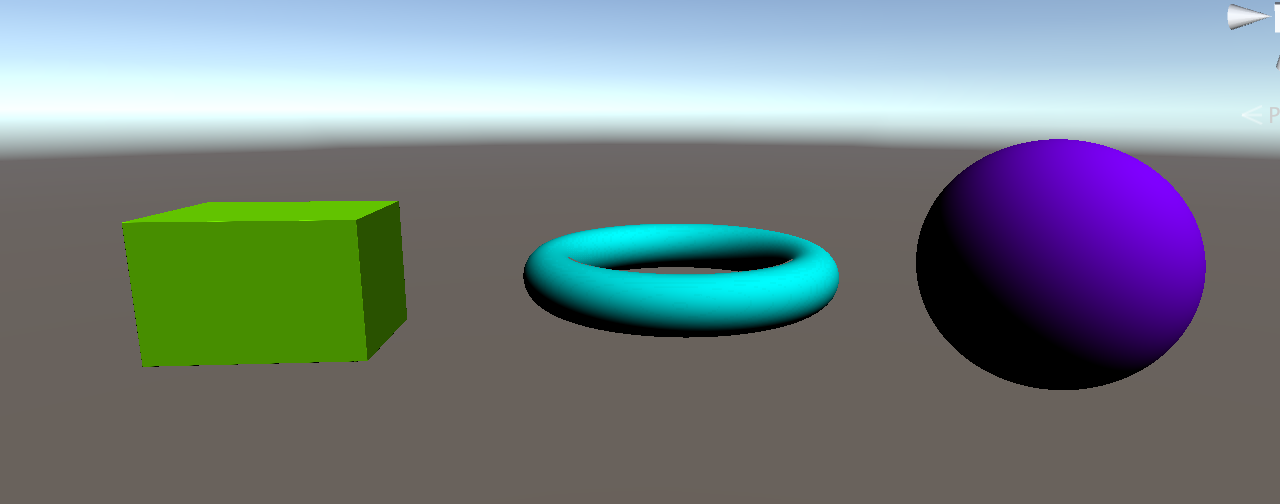
Raymarching with multiple materials
Performance Testing
It is often necessary to test the performance of your raymarch shader. The best way to do this is to see how often map() is called per frame. We can create a nice visualization of this by modifying raymarch() to output the number of samples per frame. Simply map the number of samples in a given pixel to a Color Ramp, as in the previous section.
1
2
3
4
5
6
7
8
9
10
11
12
13
14
15
16
17
18
19
20
21
22
fixed4 raymarch(float3 ro, float3 rd, float s) {
    const int maxstep = 64;
    float t = 0; // current distance traveled along ray

    for (int i = 0; i < maxstep; ++i) {
        float3 p = ro + rd * t; // World space position of sample
        float2 d = map(p);      // Sample of distance field (see map())

        // If the sample <= 0, we have hit something (see map()).
        if (d.x < 0.001) {
            // Simply return the number of steps taken, mapped to a color ramp.
            float perf = (float)i / maxstep;
            return fixed4(tex2D(_ColorRamp, float2(perf, 0)).xyz, 1);
        }

        t += d;
    }

    // By this point the loop guard (i < maxstep) is false.  Therefore
    // we have reached maxstep steps.
    return fixed4(tex2D(_ColorRamp, float2(1, 0)).xyz, 1);
}
This is what the visualization looks like in Unity:
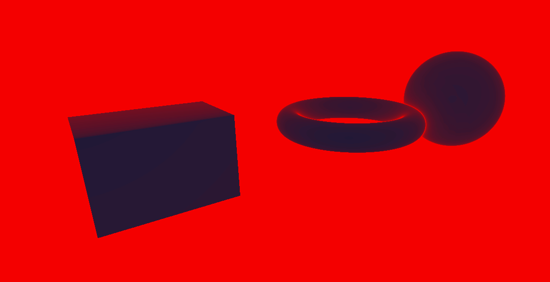
A performance visualization, with blue = lower step count and red = high step count.
The above visualization highlights a major problem in our algorithm. The pixels that do not show any raymarched objects (most pixels fall under this category) display the maximum step size! This makes sense: the rays cast from these pixels never hit anything, so they march onward forever. To remedy this performance issue, we can add a maximum draw distance like so:
1
2
3
4
5
6
7
8
9
10
11
12
13
14
15
16
17
18
19
20
21
22
23
24
25
fixed4 raymarch(float3 ro, float3 rd, float s) {
    const int maxstep = 64;
    const float drawdist = 40; // draw distance in unity units

    float t = 0; // current distance traveled along ray

    for (int i = 0; i < maxstep; ++i) {
        float3 p = ro + rd * t; // World space position of sample
        float2 d = map(p);      // Sample of distance field (see map())

        // If the sample <= 0, we have hit something (see map()).
        // If t > drawdist, we can safely bail because we have reached the max draw distance
        if (d.x < 0.001 || t > drawdist) {
            // Simply return the number of steps taken, mapped to a color ramp.
            float perf = (float)i / maxstep;
            return fixed4(tex2D(_ColorRamp, float2(perf, 0)).xyz, 1);
        }

        t += d;
    }

    // By this point the loop guard (i < maxstep) is false.  Therefore
    // we have reached maxstep steps.
    return fixed4(tex2D(_ColorRamp, float2(1, 0)).xyz, 1);
}
Here’s our heatmap after the above optimization:
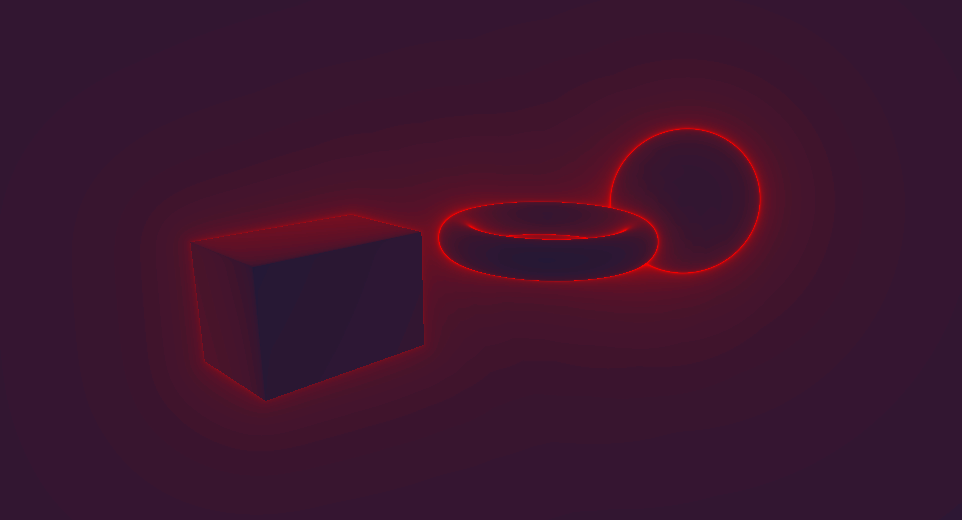
Another performance visualization after the above optimization, with blue = lower step count and red = high step count.
Much better! We can add this optimization to a normal raymarch loop by adding the draw distance check to the depth buffer culling check:
1
2
3
4
5
6
7
8
9
10
11
12
13
14
15
16
17
18
fixed4 raymarch(float3 ro, float3 rd, float s) {
    fixed4 ret = fixed4(0,0,0,0);

    const int maxstep = 64;
    const float drawdist = 40; // draw distance in unity units

    float t = 0; // current distance traveled along ray
    for (int i = 0; i < maxstep; ++i) {
        if (t >= s || t > drawdist) { // check draw distance in additon to depth
            ret = fixed4(0, 0, 0, 0);
            break;
        }

        // ...
    }

    return ret;
}
Closing Remarks
I hope that this article has given a fairly robust introduction to Distance Field Raymarching. Once again you can find a complete reference implementation at this Github Repository. If you are interested in learning more, I would suggest looking at examples on Shadertoy and at the resources referenced below. Much of the techniques used in Distance Field Raymarching are not formally documented, so it is up to you to find them. From a theoretical perspective, I haven’t touched on a whole bunch of interesting topics relating to raymarching including shadows, ambient occlusion, complex domain operations, complex procedural texturing techniques, etc. I suggest you begin to do your own research on these tricks!
References
- Inigo Quilez’s blog is in my opinion the seminal resource on Raymarching Distance fields. His articles discuss advanced raymarching techniques.
- This article in particular is a very useful reference for Distance Field functions.
- This Article by 9bit Science is a great writeup on the theory behind raymarching.
- Shadertoy is a web-based shader viewing site and hosts many striking examples of distance field raymarching (as well as other applications of raymarching such as volumetric lighting). Every shader has full source code access, so it’s a great way to learn about different techniques.
- This Gamedev Stackexchange discussion gives some interesting background into how raymarching shaders work fundamentally, and offers some alternative usecases of raymarching such as volumetric lighting.
